Configuration from Scratch
There are two methods of configuring the controller from the ground up. The first method can be done off line completely, with no connection to the controller at all. The other method requires a connection to the SC4.
METHOD 1(from scratch)
- Launch UCONV4 and locate the ‘New SC-4’ item in the upper right corner of the application and either double click it or right click it, then click the item called ‘Add Device to System’. Note: SC-4 is the name used in UCONV4 for all controller types.
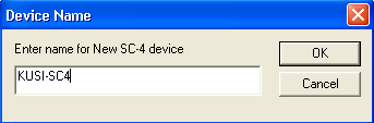
- When the following window opens, type the desired name for the controller and then click OK.
- The new controller icon will be added to the ‘System’ screen as seen below. It will have a red box around it indicating that it is offline. To open the configuration table, either double click the icon or right click on it and click the menu item called ‘Edit’.

- The following table will open with blank Router and Level tables and zeros in the MX Router Properties and Party Line Properties.
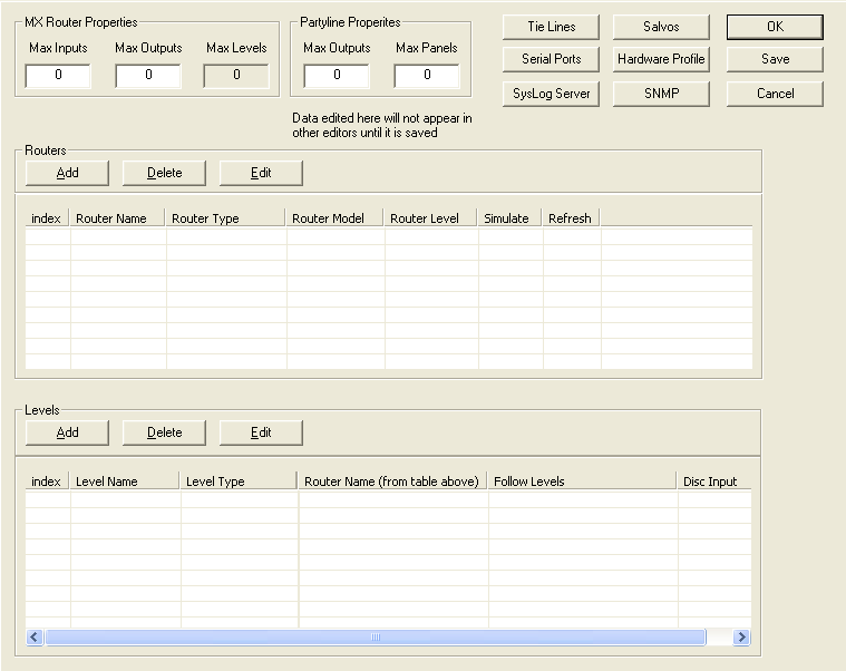
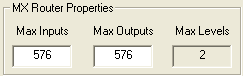
- Begin by typing in the maximum number of inputs and outputs that the controller will be capable of switching. As a rule, use the largest video or audio router, including future expansion. Example: If the largest router is video and is capable of expanding to 576, then this is the number of inputs and outputs that would be entered in the boxes. The Max Levels cannot be changed. This is generated by the number of physical levels that are created.
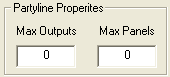
- Type in the maximum number of outputs that are to be switched on the Party Line bus and the total number of CSP Party Line control panels. This is only to be applied if there are Party Line panels to be used with the controller. Note: The Party Line is limited to 320 outputs so this is the maximum number that can be put in the box.