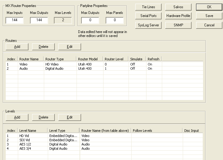
Level Table
- The level table should be filled in according to the order of the desired logical (virtual) levels and how these will be displayed in the physical control panel level display windows. The table below has a level name which can be any desired name for each level. This will appear in the source and destination tables above the level column. Each level that is added to this table will appear beginning at the top of the table and will then appear from left to right in the source and destination columns. Note: Logical levels are mapped to physical levels using these tables. This gives the ability to create multiple levels from each physical level, thus partitioning the router to different sizes.
- The level type should be as accurate as to what the physical level is.
- The router name is selected from the physical list created from the router table.
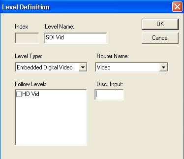
- The following table is used if there is a specific level that always needs to switch with another level such as an audio level following a video level. Note: This will only apply if there is a breakaway take on the master level at which time the other level would be married to it and they would both switch together.
- The disconnect input is a number used for that level that would automatically switch selected sources to it when it is set up this way. Example: If one source has audio and video and then a take is made to a video only source, then when that video only source is taken, the audio would switch to the disconnect input which would be whatever that disconnect input would have on it. In this case it would be silent because it would be set up to switch to a non audio source location.
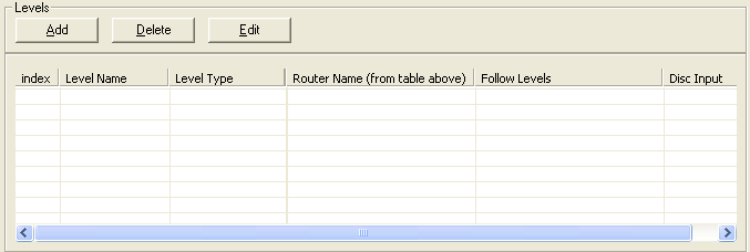
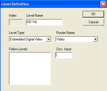
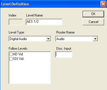
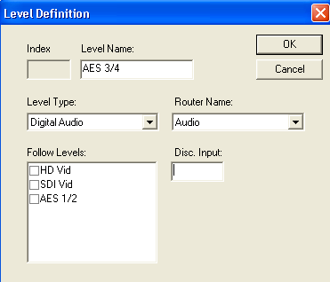
- Click the ‘Add’ button to get the tables below. This must be done for each virtual level router level. Type the desired name for the router in the ‘Level Name’ window. This can be any desired name for each level. This name will appear in the source and destination tables above the level column in the source and destination tables.
- Drop down the ‘Level Type’ menu and select the specific type of router for that level. Note: This is only critical for two types of routers. If the level is a UT300 Analog Audio left or right channel then the selection must be ‘Analog Audio Left’ and ‘Analog Audio Right’ accordingly. This is what allows the attribute functions to work on this router type. The other instance is for the UT400 Data Router type. The selection must be ‘Data Auto Disconnect’. This is required for the Data router to switch correctly.
- Click the ‘Router Name’ drop down menu and select the corresponding router type that was created in the router tables for that level.
- If desired, click on the level to be the master level in the ‘Follow Levels’ window. Note: This is generally unused.
- Type in a desired disconnect input, as explained above, in the ‘Disc Input’ window. The four figures below show the results of steps 1-5 above.
- Go to ‘File’ at the top of UCONV4 and select the ‘Save As’ item. DO NOT save this in the c:\ucondatastore folder. You must create a new location in another directory on the pc. We recommend it be saved in c:\usi\current datastore which may need to be created.