Creating New Source and Destination Devices
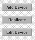
- From the ‘Sources’ or ‘Destinations’ menu screen, click the ‘Add Device’ button to the right of the table.
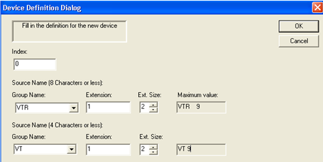
- The following table will appear with the next available index number in the top left corner. If it is the first one in the list then it will start with 0. This number can be edited here or on the main screen and cannot be duplicated. NOTE: Index numbers are the numbers that will be used in automation and Master Control. Use these numbers for the required tables in those applications. If this number matches the router number, then this will make it much easier to recall which number these applications use, as they are both the same.
- Type the name of the device group in the ‘8 character or less’ window followed by the extension to be used or drop down the arrow next to the group name and select a group. In this example, VTR is the group name and 1 is the extension. The extension size is a 2, allowing for up to 99 VTR’s to be added. This can be 0–3. Note: the name can be any alpha numeric entry including symbols. The extension can only be numbers and letters from A-F.
- Type a shortened version of the 8 character name in the 4 character name box followed by the same extension as above, or drop down the arrow to select a group.
- The drop down arrows in the group windows will show already created groups.
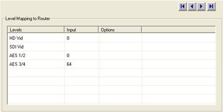
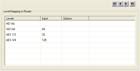
- The ‘Levels’ column in the bottom section of the same table will show the name of the assigned logical (virtual) levels. In the column to the right of this, add the physical number for that level. This is the actual number on the rear of the router, which begins at 0. The example below shows four logical levels which actually come from two physical 144 size routers. Two are video levels and two are audio levels. Since there are only two physical routers, and they are both 144 in size, then the numbers that are to be entered in the table can only be from 0-143, shared between both video levels and both audio levels. Therefore, we have partitioned the video levels into and HD level from 0-63 and an SDI level from 64-143. The same for AES ½ from 0-63 and AES ¾ from 64-143. VTR1 happens to be an HD source only so it is input 0 and it uses four channels of audio. The SDI router would then use other numbers for its level and the HD level would be blank, as seen in the 2nd figure below.
NOTE: These numbers don’t need to be partitioned as in this example. They can be any number that fits in the range for that router. Just make sure to use the input and output number only once for each device.